
A335/A335M Alloy-Steel Pipe for High-Temperature Service
Home >
-
API steel pipe
- API steel pipe
- API steel casing pipe
- Casing and Tubing
- API drill pipe
- API5L steel pipe
- Oil pipeline
-
Carbon steel pipe
- Carbon steel pipe
- Welded steel Pipe
- seamless carbon steel pipe
- Petroleum Casing Pipe
-
Alloy steel pipe
- astm a 335 gr p22
- alloy steel pipe l555
- 25crmo4 alloy steel pipe
- alloy pipe a335 p11
- interpret seamless steel pipe
- Water pipeline - Handling and
- Applications of welded pipe pil
- welded steel pipes and Seamless
- ASTM A 106 Seamless Pipe
- Carbon dioxide resistant oil ca
- seamless steel pipe On-line col
- EN 10305-1 / DIN 2391 cold draw
- EN 10255 Standard Pipe,replaces
- API 5L A53 / A106 Grade B, Seam

One of the Top 500 enterprises in China foreign trade
QCCO was approved as a member of “China Association for Contracting Projects Abroad “and granted a membership certificate on Sep 28,2005; “Credibility Rating AAA certificate in Foreign Trade” was granted to QCCO by China Shippers’ Association
A335/A335M Alloy-Steel Pipe for High-Temperature Service
Standard Specification for
Seamless Ferritic Alloy-Steel Pipe for High-Temperature Service
1. Scope
1.1 This specification 2 covers nominal (average) wall seamless alloy-steel pipe intended for high-temperature service.Pipe ordered to this specification shall be suitable for bending,flanging (vanstoning), and similar forming operations, and for fusion welding. Selection will depend upon design, service conditions, mechanical properties, and high-temperature characteristics.
1.2 Several grades of ferritic steels (Note 1) are covered.Their compositions are given in Table 1.
NOTE 1—Ferritic steels in this specification are defined as low and intermediate-alloy steels containing up to and including 10 % chromium.
1.3 Supplementary requirements (S1 to S7) of an optional nature are provided. These supplementary requirements call for additional tests to be made, and when desired, shall be so stated in the order together with the number of such tests required.
1.4 The values stated in either inch-pound units or SI units are to be regarded separately as standard. Within the text, the SI units are shown in brackets. The values stated in each system are not exact equivalents; therefore, each system must be used independently of the other. Combining values from the two systems may result in nonconformance with the specification. The inch-pound units shall apply unless the “M” designation of this specification is specified in the order.
NOTE 2—The dimensionless designator NPS (nominal pipe size) has been substituted in this standard for such traditional terms as “nominal diameter,” “size,” and “nominal size.”
2. Referenced Documents
2.1 ASTM Standards:
A 450/A 450M Specification for General Requirements for Carbon Ferritic Alloy, and Austenitic Alloy Steel Tube A 999/A 999M Specification for General Requirements for Specialized Alloy and Stainless Steel Pipe
E 213 Practice for Ultrasonic Examination of Metal Pipe and Tubing
E 309 Practice for Eddy-Current Examination of Steel Tubular Products Using Magnetic Saturation
E 381 Method of Macroetch Testing, Inspection, and Rating Steel Products, Comprising Bars, Billets, Blooms, and Forgings
E 527 Practice for Numbering Alloys and Metals (UNS)
E 570 Practice for Flux Leakage Examination of Ferromagnetic Steel Tubular Products
2.2 Other Documents:
SNT-TC-1A Recommended Practice for Nondestructive Personnel Qualification and Certification
SAE J 1086 Practice for Numbering Metals and Alloys (UNS)
3. Ordering Information
3.1 Orders for material under this specification should include the following, as required, to describe the desired material adequately:
3.1.1 Quantity (feet, centimetres, or number of lengths),
3.1.2 Name of material (seamless alloy steel pipe),
3.1.3 Grade (Table 1),
3.1.4 Manufacture (hot-finished or cold-drawn),
3.1.5 Size (NPS or outside diameter and schedule number or average wall thickness),
3.1.6 Length (specific or random),
3.1.7 End finish (Ends Section of Specification A 999/A 999M),
3.1.8 Optional requirements (Section 8, 11 and 12 of this specification. See the Sections on Hydrostatic Test Requirements and Permissible Variation in Weight for Seamless Pipe in Specification A 999/A 999M),
3.1.9 Test report required (Certification Section of Specification AA 999/A 999M),
3.1.10 Specification designation, and
3.1.11 Special requirements or any supplementary requirements selected, or both.
4. General Requirements
4.1 Material furnished to this specification shall conform to the applicable requirements of the current edition of Specification A 999/A 999M, unless otherwise provided herein.
5. Materials and Manufacture
5.1 Pipe may be either hot finished or cold drawn with the finishing treatment as required in 5.3.
5.2 Grade P2 and P12—The steel shall be made by coarsegrain melting practice. Specific limits, if any, on grain size or deoxidation practice shall be a matter of agreement between the manufacturer and purchaser.
5.3 Heat Treatment:
5.3.1 All pipe of grades shown in Table 1 except P5c, P91,P92, and P122 as provided in 5.3.2, shall be reheated and furnished in the full-annealed, isothermal annealed, or normal-ized and tempered condition. If furnished in the normalized and tempered condition, the minimum tempering temperature for Grades P5, P5b, P9, P21, and P22 shall be 1250°F [675°C],the minimum tempering temperature for Grades P1, P2, P11,P12, and P 15 shall be 1200°F [650°C].
NOTE 3—It is recommended that the temperature for tempering should be at least 100°F [50°C] above the intended service temperature; consequently, the purchaser should advise the manufacturer if the service temperature is to be over 1100°F [600°C].
5.3.2 Pipe of Grades P1, P2, and P12, either hot finished or cold drawn, may be given a final heat treatment at 1200°F [650°C] to 1300°F [705°C] instead of heat treatments specified in 5.3.1.
5.3.3 All pipe of Grades P5c shall be given a final heat treatment in the range from 1325°F [715°C] to 1375°F [745°C].
NOTE 4—Certain of the ferritic steels covered by this specification will harden if cooled rapidly from above their critical temperature. Some will air harden, that is, become hardened to an undesirable degree when cooled in air from high temperatures. Therefore, operations involving heating such steels above their critical temperatures, such as welding, flanging,and hot bending, should be followed by suitable heat treatment.
5.3.4 Grade T92 shall be normalized at 1900°F [1040°C] minimum and tempered at 1350°F [730°C] minimum as a final heat treatment.
5.3.5 Grade P122 shall be normalized at 1900°F [1040°C] minimum, and tempered at 1350°F [730°C] minimum as a final heat treatment.
5.4 Except when Supplementary Requirement S7 is specified by the purchaser, Grade P91 shall be normalized at 1900°F [1040°C] minimum, and tempered at 1350°F [730°C] minimum as a final heat treatment. Alternatively, liquid quenching and tempering is allowed for thicknesses above 3 in. when mutually agreed upon between the manufacturer and the purchaser. In this case the pipe shall be quenched from 1900°F[1040°C] minimum and tempered at 1350°F [730°C] minimum as final heat treatment.
6. Chemical Composition
6.1 The steel shall conform to the requirements as to chemical composition prescribed in Table 1.
Table 1 Chemical Composition of ASTM A335
| Grade | ASTM A335 Chemical Composition | ||||||||||
| C | Mn | P max | S max | Si | Cr | Mo | V | N | Others | ||
| P1 | 0.1-0.2 | 0.3-0.8 | 0.025 | 0.025 | 0.1-0.5 | 1.0-1.5 | 0.44-0.65 | / | / | / | |
| P2 | 0.1-0.2 | 0.3-0.61 | 0.025 | 0.025 | 0.1-0.3 | 0.5-0.81 | 0.44-0.65 | / | / | / | |
| P5 | ≤0.15 | 0.3-0.6 | 0.025 | 0.025 | ≤0.5 | 4.0-6.0 | 0.45-0.65 | / | / | / | |
| P5b | ≤0.15 | 0.3-0.6 | 0.025 | 0.025 | 1.0-2.0 | 4.0-6.0 | 0.45-0.65 | / | / | / | |
| P5c | ≤0.12 | 0.3-0.6 | 0.025 | 0.025 | ≤0.5 | 4.0-6.0 | 0.45-0.65 | / | / | / | |
| P9 | ≤0.15 | 0.3-0.6 | 0.025 | 0.025 | 0.25-1.0 | 8.0-10.0 | 0.9-1.1 | / | / | / | |
| P11 | 0.05-0.15 | 0.3-0.6 | 0.025 | 0.025 | 0.5-1.0 | 1.0-1.5 | 0.44-0.65 | / | / | / | |
| P12 | 0.05-0.15 | 0.3-0.61 | 0.025 | 0.025 | ≤0.5 | 0.8-1.25 | 0.44-0.65 | / | / | / | |
| P15 | 0.05-0.15 | 0.3-0.6 | 0.025 | 0.025 | 1.15-1.65 | / | 0.44-0.65 | / | / | / | |
| P21 | 0.05-0.15 | 0.3-0.6 | 0.025 | 0.025 | ≤0.5 | 2.65-3.35 | 0.8-1.06 | / | / | / | |
| P22 | 0.05-0.15 | 0.3-0.6 | 0.025 | 0.025 | ≤0.5 | 1.9-2.6 | 0.87-1.13 | / | / | / | |
| P23 | 0.04-0.1 | 0.1-0.6 | 0.03 | 0.01 | ≤0.5 | 1.9-2.6 | 0.05-0.3 | 0.2-0.3 | ≤0.015 | Cb(0.02-0.08) ,B(0.001-0.006) | |
| Al(≤0.03), W(1.45-1.75) | |||||||||||
| Ni(≤0.4), Ti(0.005-0.060) | |||||||||||
| P24 | 0.05-0.1 | 0.3-0.7 | 0.02 | 0.01 | 0.15-0.45 | 2.2-2.6 | 0.9-1.1 | 0.2-0.3 | ≤0.012 | Ti(0.06-0.1), Al(≤0.02) | |
| B(0.0015-0.007) | |||||||||||
| P36 | 0.1-0.17 | 0.8-1.2 | 0.03 | 0.025 | 0.25-0.50 | ≤0.30 | 0.25-0.50 | ≤0.02 | ≤0.02 | Ni(1.0-1.3), Cu(0.5-0.8) | |
| Cb(0.015-0.045), Al(≤0.050) | |||||||||||
| P91 | 0.08-0.12 | 0.3-0.6 | 0.02 | 0.01 | 0.2-0.5 | 8.0-9.5 | 0.85-1.05 | 0.18-0.25 | 0.03-0.07 | Ni(≤0.4), Al(≤0.02), Cb(0.06-0.1) | |
| Ti(≤0.01), Zr(≤0.01) | |||||||||||
| P92 | 0.07-0.13 | 0.3-0.6 | 0.02 | 0.01 | ≤0.50 | 8.5-9.5 | 0.3-0.6 | 0.15-0.25 | 0.03-0.07 | Ni(≤0.4), AL(≤0.02), Cb(0.04-0.09) | |
| W(1.5-2.0), B(0.001-0.006) | |||||||||||
| Ti(≤0.01), Zr(≤0.01) | |||||||||||
| P122 | 0.07-0.14 | ≤0.7 | 0.02 | 0.01 | ≤0.50 | 10.0-11.5 | 0.25-0.6 | 0.15-0.3 | 0.04-0.1 | Ni(≤0.5), Al(≤0.02), Ti(≤0.01) | |
| W(1.5-2.5), Cu(0.3-1.7), Zr(≤0.01) | |||||||||||
| Cb(0.04-0.1), B(0.0005-0.005) | |||||||||||
| P911 | 0.09-0.13 | 0.3-0.6 | 0.02 | 0.01 | 0.1-0.5 | 8.5-9.5 | 0.9-1.1 | 0.18-0.25 | 0.04-0.09 | Ni(≤0.4), Cb(0.06-0.1) | |
| B(0.0003-0.006),Al(≤0.02) | |||||||||||
| W(0.9-1.1),Ti(≤0.01),Zr(≤0.01) | |||||||||||
7. Workmanship, Finish, and Appearance
7.1 The pipe manufacturer shall explore a sufficient number of visual surface imperfections to provide reasonable assurance that they have been properly evaluated with respect to depth. Exploration of all surface imperfections is not required but may be necessary to ensure compliance with 7.2
7.2 Surface imperfections that penetrate more than 12 1 ⁄ 2 % of the nominal wall thickness or encroach on the minimum wall thickness shall be considered defects. Pipe with such defects shall be given one of the following dispositions:
7.2.1 The defect may be removed by grinding provided that the remaining wall thickness is within specified limits.
7.2.2 Repaired in accordance with the repair welding provisions of 7.6.
7.2.3 The section of pipe containing the defect may be cut off within the limits of requirements on length.
7.2.4 Rejected.
7.3 To provide a workmanlike finish and basis for evaluating conformance with 7.2, the pipe manufacturer shall remove by grinding the following:
7.3.1 Mechanical marks, abrasions (Note 5) and pits, any of which imperfections are deeper than 1 ⁄ 16 in. [1.6 mm].
NOTE 5—Marks and abrasions are defined as cable marks, dinges, guide marks, roll marks, ball scratches, scores, die marks, and the like.
7.3.2 Visual imperfections, commonly referred to as scabs, seams, laps, tears, or slivers, found by exploration in accordance with 7.1 to be deeper than 5 % of the nominal wall thickness.
7.4 At the purchaser’s discretion, pipe shall be subject to rejection if surface imperfections acceptable under 7.2 are not scattered, but appear over a large area in excess of what is considered a workmanlike finish. Disposition of such pipe shall be a matter of agreement between the manufacturer and the purchaser.
7.5 When imperfections or defects are removed by grinding,a smooth curved surface shall be maintained, and the wall thickness shall not be decreased below that permitted by this specification. The outside diameter at the point of grinding may be reduced by the amount so removed.
7.5.1 Wall thickness measurements shall be made with a mechanical caliper or with a properly calibrated nondestructive testing device of appropriate accuracy. In case of dispute, the measurement determined by use of the mechanical caliper shall govern.
7.6 Weld repair shall be permitted only subject to the approval of the purchaser and in accordance with Specification A 999/A 999M.
7.7 The finished pipe shall be reasonably straight.
8. Product Analysis
8.1 At the request of the purchaser, an analysis of two pipes from each lot shall be made by the manufacturer.Alot (Note 6) of pipe shall consist of the following:
| NPS Designator | |
| Under 2 | 400 or fraction thereof |
| 2 to 5 | 200 or fraction thereof |
| 6 and over | 100 or fraction thereof |
N OTE 6—Alot shall consist of the number of lengths specified in 8.1 of the same size and wall thickness from any one heat of steel.
8.2 The results of these analyses shall be reported to the purchaser or the purchaser’s representative, and shall conform the requirements specified in Table 1.
8.3 For grade P 91 the carbon content may vary for the product analysis by −0.01 % and +0.02 % from the specified range as per Table 1.
8.4 If the analysis of one of the tests specified in 8.1 does not conform to the requirements specified in6.1, an analysis of each billet or pipe from the same heat or lot may be made, and all billets or pipe conforming to the requirements shall be accepted.
9. Tensile and Hardness Requirements
9.1 The tensile properties of the material shall conform to the requirements prescribed in Table 2.
9.2 Table 3 lists elongation requirements.
9.3 Pipe of Grade P122 shall have a hardness not exceeding 250 HB/265 HV [25 HRC].
TABLE 2 Tensile Requirements
| Identificatio-n Symbol | P1, P2 | P12 | P91 | P92 | P122 | All Others |
| Tensile strength, min: | ||||||
|
ksi MPa |
55 380 |
60 415 |
85 585 |
90 620 |
90 620 |
60 415 |
| Yield strength, min: | ||||||
|
ksi MPa |
30 205 |
32 220 |
60 415 |
64 440 |
58 400 |
30 205 |
TABLE 3 Elongation Requirements
|
Elongation Requirements, All grades except P91 and P92 |
P91 and P122 | |||
| Longitudinal | Transverse | Longitudinal | Transverse | |
|
Elongation in 2 in. or 50 mm, (or 4 D ), min, %: |
||||
| Basic minimum elongation for wall 5 ⁄ 16 in. [8 mm] and over in thickness, strip tests,and for all small sizes tested in full section | 30 | 20 | 20 | . . . |
| When standard round 2-in.or 50-mm gage length or proportionally smaller size specimen with the gage length equal to 4 D (4 times the diameter) is used | 22 | 14 | 20 | 13 |
| For strip tests a deduction for each 1 ⁄ 32 -in. [0.8 mm] decrease in wall thickness below in. [8 mm] from the basic minimum elongation of the following percentage points shall be made | 1.50 A | 1.00 A | 1.00 A | . . . |
A :Table 4 gives the calculated minimum values.
9.4 Table 4 gives the computed minimum elongation values
for each 1 ⁄ 32 -in. [0.8 mm] decrease in wall thickness. Where the wall thickness lies between two values above, the minimum elongation value is determined by the following formula:
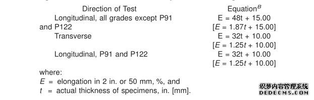
TABLE 4 Computed Minimum Elongation Values
| Wall Thickness | Elongation in 2 in. or 50 mm, min, % | |||
| All grades except P91 and P122 | ||||
| in. | mm | Longitudinal | Transverse | Longitudinal |
| 5 ⁄ 16 (0.312) | 8 | 30 | 20.0 | 20 |
| 9 ⁄ 32 (0.281) | 7.2 | 29 | 19.0 | 19 |
| 1 ⁄ 4 (0.250) | 6.4 | 27 | 18.0 | 18 |
| 7 ⁄ 32 (0.219) | 5.6 | 26 | . . . | 17 |
| 3 ⁄ 16 (0.188) | 4.8 | 24 | . . . | 16 |
| 5 ⁄ 32 (0.156) | 4 | 22 | . . . | 15 |
| 1 ⁄ 8 (0.125) | 3.2 | 21 | . . . | 14 |
| 3 ⁄ 32 (0.094) | 2.4 | 20 | . . . | 13 |
| 1 ⁄ 16 (0.062) | 1.6 | 18 | . . . | 12 |
10. Permissible Variations in Diameter
10.1 Variations in outside diameter shall not exceed those specified in Table 5.
TABLE 5 Variations in Outside Diameter Permissible Variations in Outside Diameter
| NPS Designator | Over | Under | ||
| in. | mm | in. | mm | |
| 1⁄8 to 1 1⁄2 , incl. | 1 ⁄ 64 (0.015) | 0.40 | 1 ⁄ 64 (0.015) | 0.40 |
| Over 1 1⁄2 to 4, incl. | 1 ⁄ 32 (0.031) | 0.79 | 1 ⁄ 32 (0.031) | 0.79 |
| Over 4 to 8, incl. | 1 ⁄ 16 (0.062) | 1.59 | 1 ⁄ 32 (0.031) | 0.79 |
| Over 8 to 12, incl. | 3 ⁄ 32 (0.093) | 2.38 | 1 ⁄ 32 (0.031) | 0.79 |
| Over 12 | ± 1 % | |||
11. Hydrostatic Test
11.1 Each length of pipe shall be subjected to the hydrostatic test, except as provided for in 11.2 or 11.3.
11.2 Unless otherwise specified in the purchase order, each length of pipe shall, at the option of the manufacturer, be subjected to the nondestructive electric test as shown in Section 12 in lieu of the hydrostatic test.
11.3 When specified by the purchaser, pipe shall be furnished without hydrostatic test and without nondestructive examination.
11.4 When specified by the purchaser, pipe shall be furnished with both the hydrostatic test and a nondestructive examination having been performed.
12. Nondestructive Examination
12.1 When selected by the manufacturer or when specified in the order, as an alternative to the hydrostatic test (11.2), or when secified in the purchase order in addition to the hydrostatic test (11.4), each pipe shall be examined by a nondestruc-tive examination method in accordance with Practice E 213,Practice E 309 or Practice E 570. The range of pipe sizes that may be examined by each method shall be subject to the limitations in the scope of the respective practices.
12.2 The following information is for the benefit of the user of this specification:
12.2.1 The reference standards defined in 12.8 are convenient standards for standardization of nondestructive examination equipment. The dimensions of these standards should not be construed as the minimum size imperfection detectable by such equipment.
12.2.2 Ultrasonic examination can be performed to detect both longitudinally and transversely oriented discontinuities. It should be recognized that different techniques should be employed to detect differently oriented imperfections. The examination may not detect short, deep imperfections.
12.2.3 The eddy current examination referenced in this specification has the capability to detect significant discontinuities, especially of the short abrupt type.
12.2.4 The flux leakage examination referred to in this specification is capable of detecting the presence and location of significant longitudinally or transversely oriented discontinuities. It should be recognized that different techniques should be employed to detect differently oriented imperfections.
12.2.5 The hydrostatic test of Section 11 has the capability to find imperfections of a size that permit the test fluid to leak through the pipe wall so that it may be either visually seen or detected by a loss of fluid pressure. This test may not detect very tight, through-wall imperfections, or imperfections that extend into the wall without complete penetration.
12.2.6 A purchaser interested in ascertaining the nature (type, size, location, and orientation) of discontinuities that can be detected in the specific application of these examinations should discuss this with the manufacturer of the tubular products.
12.3 Time of Examination—Nondestructive examination for specification acceptance shall be performed after all mechanical processing, heat treatments and straightening operations. This requirement does not preclude additional testing at earlier stages in the processing.
12.4 Surface Conditions:
12.4.1 All surfaces shall be clean and free of scale, dirt,grease, paint, or other foreign material that could interfere with interpretation of test results. The methods used for cleaning and preparing the surfaces for examination shall not be detrimental to the base metal or the surface finish.
12.4.2 Excessive surface roughness or deep scratches can produce signals that interfere with the test (see 12.10.2.3).
12.5 Extent of Examination:
12.5.1 The relative motion of the pipe and the transducer(s), coil(s), or sensor(s) shall be such that the entire pipe surface is scanned, except for end effects as noted in 12.5.2.
12.5.2 The existence of end effects is recognized, and the extent of such effects shall be determined by the manufacturer,and, if requested, shall be reported to the purchaser. Other nondestructive tests may be applied to the end areas, subject to agreement between the purchaser and the manufacturer.
12.6 Operator Qualifications—The test unit operator shall be certified in accordance with SNT-TC-1A, or an equivalent, recognized and documented standard.
12.7 Test Conditions:
12.7.1 For examination by the ultrasonic method, the minimum nominal transducer frequency shall be 2.25 MHz.
12.7.2 For eddy current testing, the excitation coil frequency shall be 10 kHz, or less.
12.8 Reference Standards:
12.8.1 Reference standards of convenient length shall be prepared from a length of pipe of the same grade, size (NPS or outside diameter and schedule or wall thickness), surface finish and heat treatment condition as the pipe to be examined.
12.8.2 For ultrasonic testing, the reference notches shall be any one of the three common notch shapes shown in Practice E 213, at the option of the manufacturer. The depth of the notch shall not exceed 12 1 ⁄ 2 % of the specified nominal wall thickness of the pipe or 0.004 in. (0.1 mm), whichever is greater. The length of the notch shall be at least twice the diameter of the transducer(s). The width of the notch shall not exceed the depth.
12.8.3 For eddy current testing, the reference standard shall contain, at the option of the manufacturer, any one of the following discontinuities:
12.8.3.1 Drilled Hole—The reference standard shall contain three or more holes, equally spaced circumferentially around the pipe and longitudinally separated by a sufficient distance to allow distinct identification of the signal from each hole. The holes shall be drilled radially and completely through the pipe wall, with care being taken to avoid distortion of the pipe while drilling. The hole diameter shall vary with NPS as follows:
| NPS Designator | Hole Diameter |
| 1 ⁄ 2 | 0.039 in. (1 mm) |
| above 1⁄2 to 1 1⁄4 | 0.055 in. (1.4 mm) |
| above 1 1 ⁄ 4 to 2 | 0.071 in. (1.8 mm) |
| above 2 to 5 | 0.087 in. (2.2 mm) |
| above 5 | 0.106 in. (2.7 mm) |
12.8.3.2 Transverse Tangential Notch—Using a round tool or file with a 1 ⁄ 4 in. (6.4 mm) diameter, a notch shall be filed or milled tangential to the surface and transverse to the longitudinal axis of the pipe. Said notch shall have a depth not exceeding 12 1 ⁄ 2 % of the specified nominal wall thickness of the pipe or 0.004 in. (0.1 mm), whichever is greater.
12.8.3.3 Longitudinal Notch—A notch 0.031 in. or less in width shall be machined in a radial plane parallel to the tube axis on the outside surface of the pipe, to have a depth not exceeding 12 1 ⁄ 2 % of the specified nominal wall thickness of the pipe or 0.004 in. (0.1 mm), whichever is greater. The length of the notch shall be compatible with the testing method.
12.8.4 For flux leakage testing, the longitudinal reference notches shall be straight-sided notches machined in a radial plane parallel to the pipe axis. For wall thickness less than 1 ⁄ 2 in. (12.7 mm), outside and inside notches shall be used; for
wall thicknesses equal to or greater than 1 ⁄ 2 in., only an outside notch shall be used. Notch depth shall not exceed 12 1 ⁄ 2 % of the specified nominal wall thickness or 0.004 in. (0.1 mm),whichever is greater. Notch length shall not exceed 1 in. (25.4mm), and the width shall not exceed the depth. Outside and inside notches shall have sufficient separation to allow distinct identification of the signal from each notch.
12.8.5 More or smaller reference discontinuities, or both,may be used by agreement between the purchaser and the manufacturer.
12.9 Standardization Procedure:
12.9.1 The test apparatus shall be standardized at the beginning and end of each series of pipes of the same size (NPS or diameter and schedule or wall thickness), grade and heat treatment condition, and at intervals not exceeding 4 h during the examination of such pipe. More frequent standardizations may be performed at the manufacturer’s option or may be required upon agreement between the purchaser and the manufacturer.
12.9.2 The test apparatus shall also be standardized after any change in test system settings, change of operator, equipment repair, or interruption due to power loss, shutdown or operator breaks.
12.9.3 The reference standard shall be passed through the test apparatus at same speed and test system settings as the pipe to be tested.
12.9.4 The signal-to-noise ratio for the reference standard shall be 2.5 to 1 or greater and the reference signal amplitude for each discontinuity shall be at least 50 % of full scale of the display.
12.9.5 If upon any standardization, the reference signal amplitude has decreased by 25 % (2 db), the test apparatus shall be considered out of standardization. The test system settings may be changed, or the transducer(s), coil(s) or sensor(s) adjusted, and the unit restandardized, but all pipe tested since the last acceptable standardization must be retested.
12.10 Evaluation of Imperfections:
12.10.1 Pipes producing a signal equal to or greater than the signal produced by the reference standard shall be positively identified and they shall be separated from the acceptable pipes. The area producing the signal may be reexamined.
12.10.2 Such pipes shall be subject to one of the following three dispositions:
12.10.2.1 The pipes may be rejected without further examination, at the discretion of the manufacturer.
12.10.2.2 The pipes shall be rejected, but may be repaired,if the test signal was produced by imperfections which cannot be identified, or was produced by cracks or crack-like imperfections. These pipes may be repaired by grinding (in accordance with 7.2.1), welding (in accordance with 7.6) or sectioning (in accordance with 7.2.3). To be accepted, a repaired pipe must pass the same nondestructive examination by which it was rejected, and it must meet the remaining wall thickness requirements of this specification.
12.10.2.3 Such pipes may be evaluated in accordance with the provisions of Section 7, if the test signals were produced by visual imperfections such as those listed below:
(a) Scratches,
(b) Surface roughness,
(c) Dings,
(d) Straightener marks,
(e) Cutting chips,
(f) Steel die stamps,
(g) Stop marks, or
(h) Pipe reducer ripple.
13. Mechanical Tests Required
13.1 Transverse or Longitudinal Tension Test and Flattening Test, Hardness Test, or Bend Test—For material heat treated in a batch-type furnace, tests shall be made on 5 % of the pipe from each treated lot (Note 7). For small lots, at least 1 pipe shall be tested. For material heat treated by the continuous process, tests shall be made on a sufficient number of pipe to constitute 5 % of the lot (Note 7), but in no case less than 2 pipe.
NOTE 7—The term “lot” applies to all pipe of the same nominal size and wall thickness (or schedule) which is produced from the same heat of steel and subjected to the same finishing treatment in a continuous furnace; when final heat treatment is in a batch-type furnace, the lot shall include only that pipe which is heat treated in the same furnace charge.
13.2 Hardness Test:
13.2.1 For pipe of Grade P122, Brinell, Vickers, or Rockwell hardness tests shall be made on a specimen from each lot (see Note 7).
13.3 Bend Test:
13.3.1 For pipe whose diameter exceeds NPS 25 and whose diameter to wall thickness ratio is 7.0 or less shall be subjected to the bend test instead of the flattening test. Other pipe whose diameter equals or exceeds NPS 10 may be given the bend test in place of the flattening test subject to the approval of the purchaser.
13.3.2 The bend test specimens shall be bent at room temperature through 180° without cracking on the outside of the bent portion. The inside diameter of the bend shall be 1 in [25 mm].
13.3.3 Test specimens for the bend test specified in 13.3 shall be cut from one end of the pipe and, unless otherwisee specified, shall be taken in a transverse direction. One test specimen shall be taken as close to the outer surface as possible and another from as close to the inner surface as possible. The specimens shall be either 1 ⁄ 2 by 1 ⁄ 2 in. [12.5 by 12.5 mm] in section or 1 by 1 ⁄ 2 in. [25 by 12.5 mm] in section with the corners rounded to a radius not over 1 ⁄ 16 in. [1.6 mm] and need not exceed 6 in. [150 mm] in length. The side of the samples placed in tension during the bend shall be the side closest to the inner and outer surface of the pipe, respectively.
14. Certification
14.1 In addition to the information required by Specification A 999/A 999M, the certification shall state whether or not the material was hydrostatically tested. If the material was nondestructively examined, the certification shall so state and shall show which practice was followed and what reference discontinuities were used. In addition, the test method information as given in Table 3 shall be appended to the specification number and grade shown on the certification.
15. Product Marking
15.1 In addition to the marking prescribed in Specification A 999/A 999M, the marking shall include the length, an additional symbol “S”, if the pipe conforms to any of the Supplementary Requirements S1 to S6, the ANSI schedule number and the heat number or manufacturer’s number by which the heat can be identified. Furthermore, the marking designated in Table 6 to indicate the test method(s) shall be included. Marking may be by stenciling, stamping, or rolling.Pipe that has been weld repaired in accordance with 7.6 shall be marked “WR.”
TABLE 6 Test Method Information for Certification and Marking
| Hydrostatic | Nondestructive | Marking |
| YES | NO | Test Pressure |
| NO | YES | NDE |
| NO | NO | NDE |
| YES | YES | Test Pressure/NDE |
16. Government Procurement
16.1 Scale Free Pipe:
16.1.1 When specified in the contract or order, the following requirements shall be considered in the inquiry contract or order, for agencies of the U.S. Government where scale free pipe or tube is required. These requirements shall take precedence if there is a conflict between these requirements and the product specification.
16.1.2 The requirements of SpecificationA 999/A 999M for pipe and Specification A 450/A 450M for tubes shall be applicable when pipe or tube is ordered to this specification.
16.1.3 Pipe and tube shall be one of the following grades as specified herein:
| Grade | UNS Designation |
| P11 | K11597 |
| P11 | K21590 |
| P5 | K41545 |
16.1.4 Part Number:
16.1.4.1 Pipe shall be ordered to nominal pipe size andschedule specified in ANSI B36.10
Example: A 335/A 335M Pipe P-11 NPS 12 Sch 40
| Specification Number | ASTM A 335/A 335M |
| Pipe | P |
| Grade | P-11 |
| NPS | 12 |
| Wall | 0.375 |
16.1.4.2
| Specification Number | ASTM A 335/A 335 M |
| Tube | T |
| Grade | P-11 |
| Ouside Diameter | 0.250 |
| Wall | 0.035 |
16.1.4 Part Number:
16.1.4.1 Pipe shall be ordered to nominal pipe size andschedule specified in ANSI B36.10
16.1.5 Ordering Information—Orders for material under this specification shall include the following in addition to the requirements of Section 4:
16.1.5.1 Pipe or tube,
16.1.5.2 Part number,
16.1.5.3 Ultrasonic inspection, if required,
16.1.5.4 If shear wave test is to be conducted in two opposite circumferential directions.
16.1.5.5 Level of preservation and packing required.
17. Keywords
17.1 alloy steel pipe; high temperature service; seamless steel pipe; steel pipe; temperature service applications.
上一篇:General structure steel pipe
下一篇:ASTM A53/A106/API 5L GR.B /X42 Seamless Carbon Steel Pipe